Manufacturing small, intricate metal components economically challenges engineers across every industry. MIM parts solve this problem by combining plastic injection molding flexibility with metal material performance. This guide explains the technology and helps you understand its benefits.
What is MIM Parts
MIM parts are metal components produced through Metal Injection Molding, a process that mixes fine metal powder with a plastic binder to create a moldable feedstock. This feedstock is heated and injected into a mold cavity just like plastic. The molded part then undergoes debinding to remove most of the binder. Finally, the remaining metal skeleton is sintered at high temperature to achieve full density.
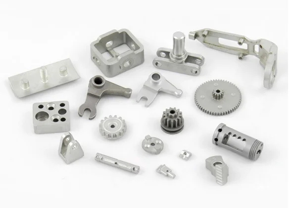
The result is a fully dense metal component with mechanical properties approaching wrought materials. MIM metal parts achieve complex three-dimensional geometries impossible with conventional powder metallurgy. The process produces small components typically weighing less than 100 grams. Industries including medical devices, firearms, aerospace, consumer electronics, and automotive sensors depend on this technology. MIM metal parts combine the design freedom of plastic injection molding with the strength and durability of metal.
Related: Key Design Considerations for MIM Parts
Successful production requires thoughtful design that accounts for the unique characteristics of the metal injection molding process. Understanding these principles helps you create components that manufacture reliably.
Wall thickness uniformity is critical for MIM metal parts. During debinding and sintering, the component shrinks 15 to 20 percent linearly. Uneven wall thickness causes differential shrinkage that leads to warping, internal voids, or cracking. Designers should maintain consistent wall thickness throughout the part whenever possible. If thick sections are structurally necessary, consider coring them out to create uniform walls.
Draft angles enable clean ejection from the mold. Vertical walls without draft create friction during part removal, potentially damaging the delicate green component. Include at least 0.5 to 1 degree of draft on all surfaces parallel to the mold opening direction. Generous draft angles reduce scrap rates and improve dimensional consistency in MIM parts.
Gate location affects material flow and final properties. The gate is where molten feedstock enters the mold cavity. Its position influences how the material fills the cavity and how weld lines form. Poor gate placement creates weak spots or surface defects. Experienced MIM manufacturers use mold flow simulation software to optimize gate locations before cutting tooling.
Undercuts and complex features that would require slides or lifters in the mold add cost. While MIM parts can achieve more complex geometries than conventional powder metallurgy, simplifying the mold design reduces tooling expense. Discuss feature necessity with your manufacturer during the design phase to balance functionality against cost.
Related: Quality Control and Testing for MIM Parts
Ensuring consistent quality requires rigorous inspection throughout production. Understanding these procedures helps you evaluate potential manufacturing partners.
Density measurement verifies full densification. MIM parts should achieve 95 to 99 percent of theoretical density after sintering. Technicians use the Archimedes method or helium pycnometry to measure actual density. Low density indicates incomplete sintering or excessive residual porosity that compromises mechanical properties.
Dimensional inspection uses coordinate measuring machines and optical comparators. MIM parts undergo significant shrinkage during sintering, and the tooling must compensate precisely. First article inspection reports document every critical dimension before production approval. Ongoing statistical process control tracks dimensional trends and detects process drift early.
Mechanical testing validates strength and ductility. Tensile test bars produced from the same feedstock lot verify yield strength, ultimate tensile strength, and elongation. Hardness testing confirms proper heat treatment response. For critical applications, fatigue testing evaluates long-term durability under cyclic loading.
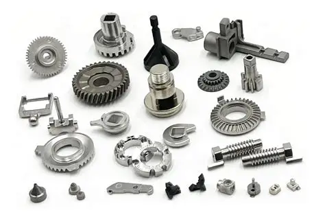
Metallographic examination reveals internal structure. A cross-section of the part is polished and examined under a microscope. The microstructure shows grain size, phase distribution, and any residual porosity. Properly processed MIM parts exhibit fine, uniform grains with minimal inclusions or defects.
Non-destructive testing detects internal flaws. Dye penetrant inspection reveals surface cracks. X-ray or CT scanning identifies internal voids or inclusions. These methods are essential for safety-critical MIM parts in aerospace and medical applications.
Related: Comparing MIM Parts to Alternative Manufacturing Methods
Understanding how this technology compares to other processes helps you make informed manufacturing decisions for your components.
MIM parts versus CNC machining represents a common decision point. Machining removes material from solid bar stock using cutting tools. It offers excellent precision for low volumes without tooling investment. However, machining complex geometries is slow and wastes significant material. MIM parts achieve intricate shapes in high volumes at lower per-part cost. For production above 10,000 pieces annually with complex geometry, MIM typically costs far less than machining.
MIM parts versus conventional powder metallurgy involves different capability boundaries. Conventional pressing produces simple to moderate complexity shapes economically in high volumes. However, it cannot create undercuts, cross-holes, or complex three-dimensional contours because parts must eject from a rigid die. MIM parts overcome this limitation through the injection molding process. The trade-off is higher cost due to more expensive feedstock and additional debinding steps.
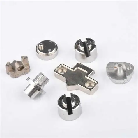
MIM parts versus investment casting compares two near-net-shape processes. Casting pours molten metal into ceramic molds. It handles larger parts and a wider range of alloys. However, casting produces rougher surfaces and lower dimensional accuracy. MIM parts achieve better surface finish and tighter tolerances. The finer microstructure from powder processing often yields superior mechanical properties compared to cast structures.
MIM parts versus metal additive manufacturing reflects different production scales. Additive manufacturing builds parts layer by layer from powder or wire. It offers maximum design freedom without tooling. However, it is slow and expensive for production quantities. MIM parts become far more economical at volumes above several thousand pieces. The two technologies complement each other, with 3D printing serving prototyping and MIM handling production.
FAQ: Your MIM Parts Questions Answered
1. What is the typical lead time for custom MIM parts?
Mold design and fabrication requires six to ten weeks. Prototype sample production adds three to four weeks including debinding and sintering. After prototype approval, production quantities ship within four to six weeks. Complex multi-cavity molds or parts requiring extensive secondary finishing take longer. Discuss lead times early with your manufacturer and include buffer in your project schedule.
2. What materials are available for MIM parts?
Common materials include stainless steels like 316L and 17-4PH, low alloy steels, tool steels, titanium alloys, and copper alloys. Some high-performance superalloys are also available. Not every alloy works with the process. The feedstock formulation must balance powder loading, flow properties, and sinterability. Consult your manufacturer about material options for your specific application.
3. Can MIM parts be heat treated or plated?
Yes, fully dense MIM parts accept standard finishing processes. Heat treatment including quenching, tempering, and case hardening modifies mechanical properties. Electroplating, passivation, and painting enhance appearance and corrosion resistance. The high density of properly processed MIM parts allows these treatments without the absorption problems that affect porous powder metal components.
Conclusion
MIM parts offer an exceptional combination of design flexibility and material performance for small, complex components. The process produces fully dense metal parts with mechanical properties approaching wrought materials. Understanding design principles, quality control procedures, and process comparisons helps you decide when MIM parts suit your application. Whether you need intricate medical instruments, durable firearm components, or lightweight aerospace parts, this proven manufacturing technology delivers precision and value for demanding applications.
7 Ways to Find Reliable Manufacturers of Powdered Metal Components